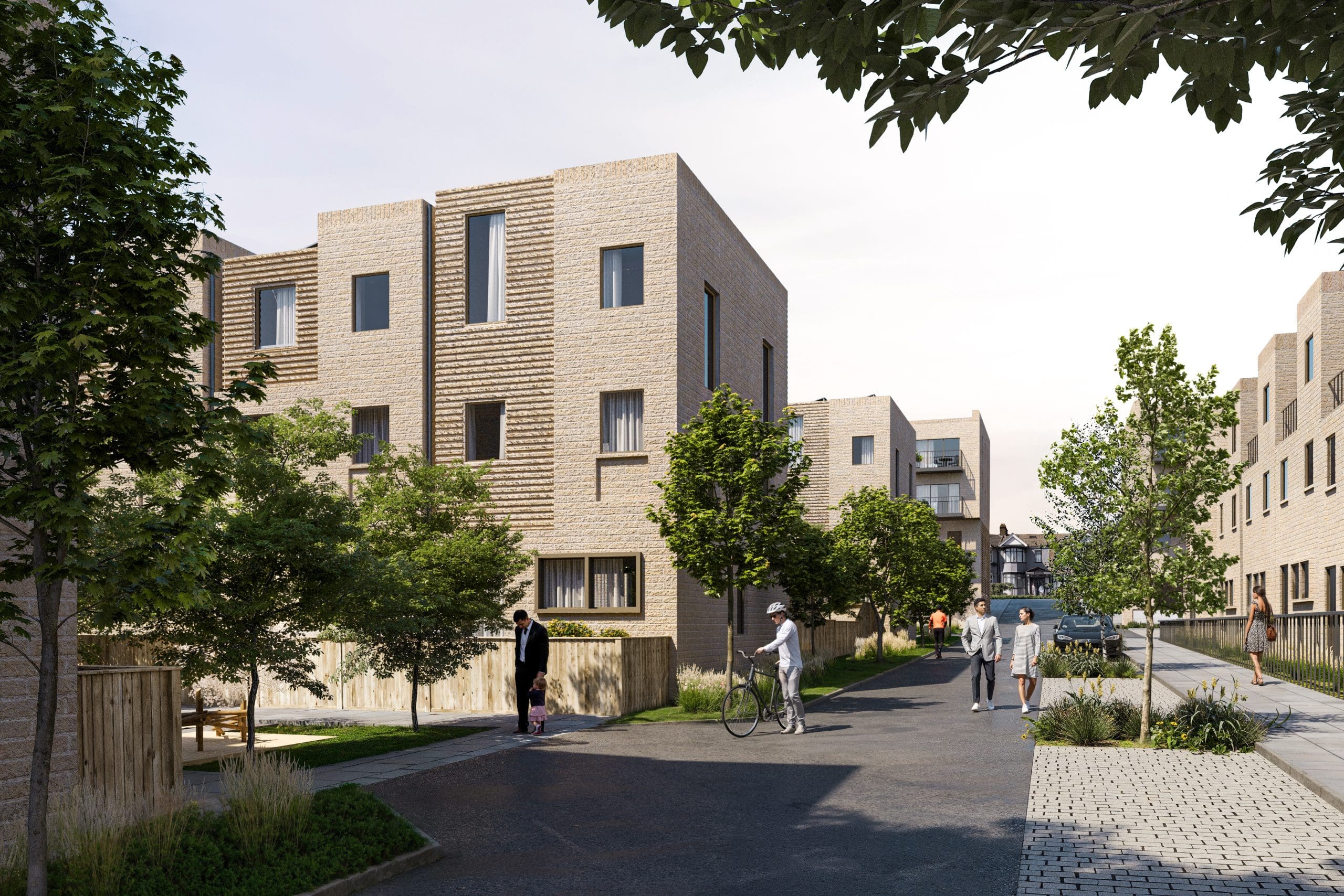
SuDS Strategy for Major Housing Development
Designed a comprehensive SuDS scheme for 350 homes, achieving SAB adoption-ready standards and reducing underground storage by 40%.
Project challenges
A 350-home scheme on greenfield land on the outskirts of Bristol presented a demanding drainage brief. The site sloped from south to north with a fall of approximately 15 metres across the 12-hectare area, creating complex surface water flow paths that the masterplan needed to respect. The underlying geology was predominantly Bristol Lias Clay, which effectively ruled out infiltration as a primary discharge mechanism.
The lead local flood authority (North Somerset Council) required the surface water discharge rate to be limited to the greenfield runoff rate for all return periods up to the 1 in 100 year event plus 45% climate change allowance. The Wessex Water public sewer network had limited capacity, and the nearest watercourse — a small ordinary watercourse along the northern boundary — was already under pressure from upstream development.
The initial drainage design prepared by a previous consultant relied on a 4,500 cubic metre geocellular underground storage tank beneath the main car parking area, with minimal above-ground SuDS features. The LLFA rejected this design on the basis that it failed to demonstrate a SuDS management train approach and did not provide the water quality treatment, amenity, or biodiversity benefits required by national and local policy.
How we solved it
We redesigned the drainage strategy from scratch, working from the SuDS management train hierarchy and integrating the drainage design into the landscape and masterplan rather than treating it as a separate engineering exercise.
At source control level, we specified permeable block paving for all private driveways and parking courts (approximately 8,000 square metres), which provided both attenuation and first-stage pollutant removal. Roof runoff from all dwellings was directed to individual rain gardens in front gardens, providing second-stage treatment and visible SuDS features at the plot level.
At site control level, we designed a series of roadside swales along the primary and secondary streets, collecting runoff from the highway and conveying it slowly northwards following the natural fall of the site. The swales incorporated check dams at regular intervals to reduce velocities on the steeper southern sections and provided distributed attenuation throughout the site.
At regional control level, we designed a landscaped detention basin and shallow wetland at the northern boundary of the site, adjacent to the receiving watercourse. The basin provided the final stage of attenuation and treatment before discharge, and the permanent wetland zone provided year-round biodiversity habitat and visual amenity for the adjacent open space.
The redesigned scheme reduced the underground storage requirement from 4,500 cubic metres to 2,700 cubic metres — a 40% reduction — by distributing attenuation through the above-ground SuDS features. The remaining underground storage was provided by oversized pipes beneath the main access road, avoiding the need for a dedicated tank structure.
Results delivered
Full planning was granted with the LLFA confirming that the revised drainage strategy met all of their requirements. The LLFA's consultation response specifically commended the management train approach and the integration of SuDS features into the landscape design.
The client reported that the redesigned SuDS scheme was cost-neutral compared to the original underground tank design — the savings from the 40% reduction in underground storage offset the cost of the above-ground SuDS features, while the permeable paving specification replaced what would have been conventional block paving at a modest cost uplift.
The detention basin and wetland at the northern boundary became a valued feature of the development, providing a focal point for the open space network and supporting the development's biodiversity net gain assessment. The swales along the primary streets created a distinctive streetscape that contributed to the design quality of the scheme.
Project Overview
This project demonstrates a pattern we see regularly: a drainage design that has been rejected by the LLFA because it fails to follow the SuDS management train approach. The original design was technically competent in engineering terms — the underground tank would have provided the required attenuation volume — but it missed the wider objectives that modern SuDS policy demands: water quality treatment, amenity, and biodiversity.
Our brief was to redesign the drainage strategy to achieve LLFA approval while maintaining the client’s construction programme and budget. The key to achieving this was integrating the drainage design into the landscape and masterplan, rather than treating surface water management as a standalone engineering problem.
Site Constraints
The site presented three significant constraints that shaped the drainage design:
Topography. The 15-metre fall across the site from south to north created steep gradients that could generate high-velocity surface water runoff during storm events. The drainage design needed to manage these velocities through the management train, preventing erosion and ensuring that downstream features received controlled inflows.
Geology. The Bristol Lias Clay underlying the site had infiltration rates of less than 1 x 10^-7 m/s, confirmed through BRE365 soakaway testing at six locations across the site. Infiltration-based SuDS features (soakaways, unlined permeable paving, infiltration basins) were not viable as the primary discharge mechanism. All SuDS features were designed as lined or tanked systems discharging to the receiving watercourse via flow control devices.
Receiving watercourse capacity. The ordinary watercourse along the northern boundary was already conveying runoff from upstream development, and the LLFA expressed concern about additional flows. The agreed discharge rate was the pre-development greenfield runoff rate of 12.5 litres per second for the 1 in 100 year event, calculated using the FEH statistical method. This low discharge rate required significant on-site attenuation — approximately 6,800 cubic metres across all return periods with climate change allowance.
The Management Train in Practice
Source Control
Permeable block paving was specified for all private driveways and visitor parking courts, covering approximately 8,000 square metres. The paving was laid on a 400mm deep Type 3 sub-base that provided approximately 1,200 cubic metres of storage within the paving structure itself. Although the clay subgrade prevented infiltration, the sub-base acted as a lined reservoir, releasing stored water slowly via perforated pipes connected to the downstream swale network.
Rain gardens in front gardens received roof runoff from individual dwellings via downpipe disconnection. Each rain garden was sized to accommodate the roof area of its associated dwelling and was planted with a mix of native and ornamental species tolerant of periodic inundation. The rain gardens provided both source-level attenuation and first-stage water quality treatment through filtration and biological uptake.
Site Control
A network of roadside swales along the primary and secondary streets collected highway runoff and conveyed it northward, following the natural fall of the site. The swales were designed with a trapezoidal cross-section, 300mm deep with 1:3 side slopes, and a base width of 600mm. Check dams at 30-50 metre intervals reduced flow velocities on the steeper sections and created a sequence of small storage compartments along each swale.
The swales served triple duty: surface water conveyance, distributed attenuation, and water quality treatment. The vegetated surfaces filtered particulates, absorbed dissolved pollutants through biological uptake, and provided a green corridor along each street that softened the appearance of the development.
Regional Control
The detention basin at the northern boundary of the site was the final attenuation and treatment stage before discharge to the receiving watercourse. The basin was designed as a dual-function feature: a shallow, permanently wet wetland zone (approximately 800 square metres) providing year-round habitat, surrounded by a deeper detention zone that fills during storm events and drains down within 48 hours.
The basin outlet was controlled by a vortex flow control device set to limit discharge to the agreed 12.5 litres per second. An emergency overflow weir was provided at the maximum design water level, directing any exceedance flow towards the open space corridor along the northern boundary.
Results
The redesigned drainage strategy provided the full 6,800 cubic metres of attenuation required, distributed across the management train: approximately 1,200 cubic metres in the permeable paving sub-base, 800 cubic metres in the rain gardens, 1,100 cubic metres in the swale network, 2,700 cubic metres in the oversized pipe system beneath the main access road, and 1,000 cubic metres in the detention basin.
By distributing attenuation through above-ground features, we reduced the underground storage requirement by 40% compared to the original design. This reduction, combined with the elimination of the large geocellular tank, provided a net cost saving that offset the additional cost of the above-ground SuDS features.
The LLFA’s approval was received without objection, and the drainage strategy was commended as an exemplar of the management train approach in their consultation response.
Related projects
Capital Gate, Ilford
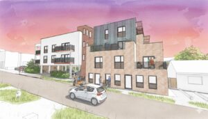
Navigated complex surface water risks and Sequential Test changes to secure planning approval for a residential redevelopment in a Critical Drainage Area.

Dew Drop Inn, Peacehaven
Managing complex surface water flood risk to deliver a safe, resilient, and policy-compliant mixed-use redevelopment on a challenging coastal site.
SuDS Strategy for Major Housing Development
Designed a comprehensive SuDS scheme for 350 homes, achieving SAB adoption-ready standards and reducing underground storage by 40%.